Insights
Explore acoustic engineering practices, industry insights and company updates.

Explore acoustic engineering practices, industry insights and company updates.
Coordinate motor speed and load requirements with loading equipment, cooling, sample changeovers and guarding when planning an acoustic development laboratory.
Plan mounting fixtures, extraction and recirculation modes, duct routes and sample changeovers for a range-hood development acoustic laboratory.
Define reference speech, target-device audio and intended room conditions before planning an R&D recording laboratory, then verify the required channels and files with a small trial recording.
For industrial-site expansions in China, compare retained, modified and new noise controls using equipment layout, realistic operating combinations, assessment locations and a defined verification plan.
Plan consumer ANC headphone R&D around controlled noise reproduction, suitable test fixtures, fitting procedures and measurement space, with a clear scope for comparing laboratory proposals.
Can hearing-aid product electroacoustic tests and real-ear measurements share a room? Plan the laboratory around what is measured, who participates and how systems are arranged, with distinct environmental, spatial and operational responsibilities.
An acoustic laboratory for washing-machine development needs more than a quiet room. Plan test textiles, programmes, appliance installation and water services as a complete workflow.
Plan an R&D acoustic laboratory around representative printing, copying and scanning tasks, separating standard configurations from optional expansion and allowing for the complete operating envelope.
A solution overview for R&D and laboratory construction teams comparing integrated proposals: define the test boundaries of a pump alone, a pump unit or a pumping system including piping, and coordinate the test circuit, acoustic space and equipment interfaces.
A solution overview coordinating pre-operation, environmental support, acoustic measurements and state records around refrigerator cooling, refrigeration and defrosting.
A solution overview connecting workpiece preparation, measurement space, operating support and changeovers to assess whether different power-tool categories can share an acoustic laboratory.
A practical overview of matching acoustic test boxes to representative devices, measurement equipment and daily R&D tasks, with clear limits on their use.
Plan the test surface, product operation, acoustic measurement space and sample preparation together for dry-vacuum-cleaner R&D, while keeping noise testing distinct from cleaning-performance testing.
Use acoustic simulation in pre-construction proposal reviews by understanding the analysis conditions, design differences and deliverables behind the results.
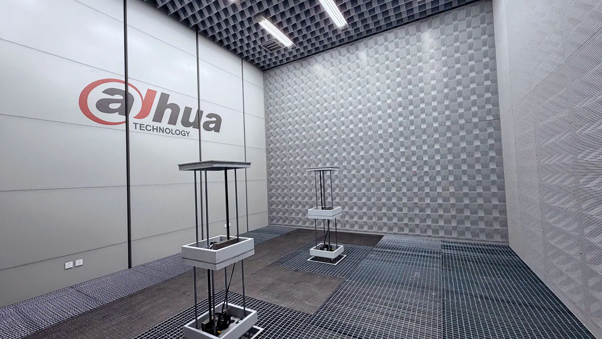
The Dahua acoustic laboratory in Hangzhou has been delivered with a cut-off frequency of ≤50 Hz, background noise below 10 dB(A) and fully automated lifting platforms, bringing together Lessent’s calculation, simulation and engineering capabilities.
Plan an acoustic laboratory around whole-system tests for computers, workstations and servers, coordinating operating states, acoustic space, power, networking and cooling with development needs.
Plan industrial acoustic enclosures around equipment operation, heat removal, staff tasks and maintenance.
An accessible overview of how EMC laboratory space, equipment arrangements and operating workflows support product development.
A look at LESSENT’s iFLYTEK laboratory project and how different acoustic spaces support voice-interaction and in-car audio development.
Start with the product port and test method, then compare impedance, frequency range and conditional current and voltage ratings. Similar bandwidth or a shared product family does not establish interchangeability.
Before testing a brief mechanical action, distinguish single-event sound energy level from average sound power level and agree event boundaries, recording arrangements and reviewable deliverables.
A dodecahedral shape does not establish measurement suitability. When procuring a system for reverberation-time or building-acoustics measurements, check the method, band-specific directivity, output margin and actual configuration.
When room noise approaches the measurement chain’s lower limit, a low reading alone may not establish room performance. Check the microphone, preamplifier, power supply and acquisition configuration, together with frequency bands and weighting.
Insertion-loss curves describe specific test conditions. Filter selection also requires checks of impedance, voltage and current ratings, loads, temperature, leakage-current protection and installation bypass paths.
Reverberation time and broadband results alone do not establish suitability for tonal-source sound power measurements. Check the method, signal type, bands and room qualification records.
TEM or GTEM suitability is not established by a sample fitting inside. Check the accepted test method, complete configuration, usable test space and intended use of the results.
Average reverberation time cannot independently diagnose narrow-band bass anomalies. Distinguish frequency response, decay and ideal modal models to make listening-room remediation and acceptance verifiable.
When a hemi-anechoic room receives a new finish or removable floor, assess structural safety and acoustic suitability separately. Define the construction, coverage and measurement configuration before deciding what verification is needed.
For laboratories planning sound power comparison measurements, check band data, installation, operating conditions and uncertainty against the intended method before accepting a reference sound source.
Panel sound reduction ratings and whole-enclosure insertion loss describe different quantities. Check sound pressure versus sound power, source conditions and test methods before comparing reports.
Two absorption reports for the same material may represent different incidence conditions and specimen boundaries. Check the method, mounting assembly and application limits before comparing curves.
Review EMC chamber acceptance evidence by measurement use, separating shielding effectiveness from NSA and SVSWR and checking the frequency range, test volume and method covered.
Amplitude calibration alone does not establish suitability for beamforming or transfer-function analysis. Separate sampling-clock synchronization, path delay, and sensor phase response before verifying the intended configuration.
As rotational speed changes, noise peaks move along the frequency axis. Order analysis relates frequency to the speed of a reference shaft, helping reveal rotation-related components. Reliable conclusions still depend on the speed signal, processing parameters, and controlled comparison tests.
Brief peaks during startup, impacts, or changes in operating conditions can overload the acquisition chain even when the average sound level is still relatively low. When setting the input range, check signal peaks alongside the capabilities of the microphone and preamplifier, and retain trial-run and overload records.